|
3D Display Designs
|
During my
employment at Actuality Systems from 2003-2006, I worked as an optical
and
software engineer, and managed a NIST funded intiative to design and
build next generation 3D displays. Below is a brief description of a
few of the designs that I had a large part in developing.
|
High Resolution Spatial Multiplexing for
Lenticular-based 3D
Lenticular 3D displays utilize a cylindircal lens array placed in front
of a 2D imaging device such as an LCD screen. Each cylindircal lens
covers a set of columns in the displayed image, and each of these
columns is converted by the lens from spatial to angular information.
The technique is conventient because it produces a very compact optical
package. However, it also produces a 3D effect at the cost of reduced
spatial resolution. In an attempt to build a 3D display with XGA
1024x768 resolution, we developed a projection engine capable of
displaying 25 megapixel images, allowing a XGA lenticular 3D image to
be displayed at XGA resolution. The technique works by sequentially
scanning 25 XGA images from a high speed DMD projector, producing a
composite high resolution image that can is refreshed at video rates.
The system consists of a Catadioptric relay system that projects a unit
magnification image from a 3-chip DMD engine onto an image scanning
module. The scanning module applies a sub-pixel comb filter to the
image that is shifted as a function of time. The motion of the filter
is synchronized with the images displayed on the DMD, allowing subpixel
information to be sequentially filled in, creating a composite
high-resolution image.
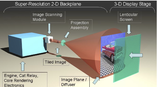 |
A system diagram of
the spatial-multiplexing 3D display concept.
|
 |
|
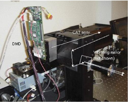
The
projection
engine
used
to implement the super-resolution 2-D backplane
from the system diagram above.
|
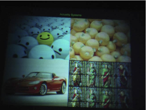
A
20
Megapixel
image
displayed using the projection engine shown on the
right.
|
Scanning Lens Array for View-Sequential 3D
We developed a method to scan the exit pupil of an imaging system for
the purpose of projecting view-dependent imagery for the 3D display.
The scanning system consists of screen made up of two lenticular or
fly's eye lens arrays placed back-to-back at the image plane of a
projection system. The dual lens array screen acts as a field lens
according to a principle originally discovered by Denis Gabor (sometime
referred to as the Gabor
superlens effect). When the optical axis of the two lens arrays are
misalgned, the entrance pupil is shifted, and thus the entrance pupil
can effectively be scanned by moving one array relative to the other.
When lens array movement is applied in synchronization with a
high-speed DMD projector, view-dependent 3D imagery can be
displayed.
 |
|
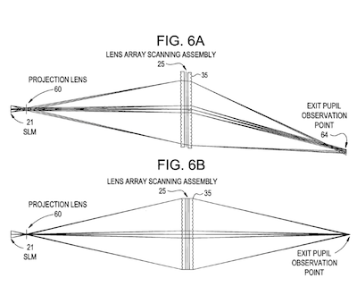
A
Gabor
superlens
scanning
system. In the bottom figure, the optical axis
of the two lens arrays is aligned, in the top figure, the axis are
misaligned, and the exit pupil image is shifted.
|
The
voice
coil
actuator
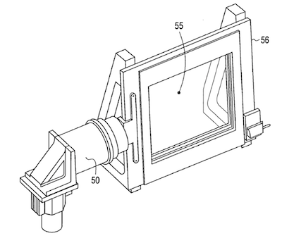
driven scanning assembly used to shift one of the
lens arrays relative to the other at high frequencies.
|
Scanning Optics for Multi-projector 3D display
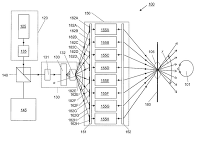
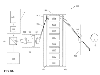
We developed a method to sequentially tile projected images from a 2D
lens to create the equivalent of 32 projectors from a single high-speed
DMD projection system. A DMD projector is fed to a galvonometric
scanner that translates the projected image as a function of time,
tiling several images sequentially to produce a very high resolution
image strip. The image strip is fed to an array of projection
lenses that essentially form a synthetic aperture
through which an observer can view 3D imagery.
 |
|
The
complete
3D
display system. On the left, a projection system is fed to
a galvonometer that imposes a translation in the projected image as a
function of time.
|
An
image
from
the projection engine is fed sequentially to each projection
lens in the array. A high speed projector is used to that each
projection lens is updated fast enough to avoid flicker.
|
|
|
|


